
Return to Special Interest page
Gambier Bay Wins Awards
(2001)
|
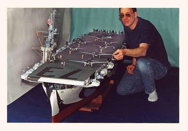
A few years ago, six to be exact, I fell heir to a book entitled "The Men of the Gambier Bay", by Edwin Hoyt. It told the story of the Casablanca Class Escort Carrier (U.S.S. Gambier Bay) and her crew. The story begins with her launch in November 1943, and ends with her loss in October 1944 with the Taffy 3 squadron at Leyte Gulf. This book sparked my interest in the history of this class of carrier and the role they played in World War II. I began research to find any and all available information on the Casablanca Class Carriers. Since none of this class remains today (and it's been over 50 years since the end of the war), the task was an uphill battle for me. With some help, I found a Survivor's Association for Taffy 3. After my first contact with them, an avalanche of photos and information started rolling in. A set of plans was obtained from "The Floating Dry-dock". Several more books on Allied Escort Carriers were purchased. By good luck, a set of micro-film records of the builder's original plans was located and copies made. Then I made a trip to the Newport News Maritime Museum to view their photo archives. This gave me all the additional information I would need to build the model. I made the decision to build this particular ship because of all of the help from the Survivor's Association and also because the U.S.S. Gambier Bay was the only U.S. Navy Aircraft Carrier lost to a surface action during the war. By this time, I had put in almost two years of research on the model and still not a single thing had been built yet. The next step, deciding what scale to build the model in, was almost as complex a decision as the model building itself. After weighing all of the pluses and minuses, I chose a scale of quarter inch to the foot (1/48). This scale would allow me to show the maximum detail and still be transportable. Overall, at 1/48 scale the hull would be ten feet six inches in length with a beam of 16 1/4 inches at the center. Choosing a stable material for the keel was the next very important step. Because the keel would be over ten feet in length, several materials were discussed, including metal. It was decided, for ease of construction and fabrication, to use a one-piece section of old growth red oak. Quarter inch thick, 7 ply marine plywood was used to build the 61 individual frames that make up the shape of the hull. Stringers, reinforcement plates, and spacers were made from laminated pine. Each of the hull frames had two 1/16-inch diameter holes drilled through and centered above where the keel and frame interlocked. Two laser pointers were then used to align the frames with the centerline of the keel. This same system was used as all the stringers and spacers were attached. The outcome was a level, straight, and strong hull frame. The full sides and bottom were made from 11/32 inch plywood in 48 inch lengths. Each end of the plywood panel was machined to 1/2 its own thickness. This was done so that when it was attached to the hull, it would form a lap joint where it met with the next panel. This formed a very strong and secure joint. The shape and location for the bilge keels were found and, using plywood, the basic shape was glued to the hull. All glue joints were made with either CA+ Thick or Yellow Carpenters Glue. Polyester resin over epoxy would not properly harden and would also cause problems later on. Two coats of 2 oz. Fiberglass cloth with polyester resin were applied to the hull. A light sanding was done between coats. After the second coat set-up, the hull was wet sanded, any imperfections were filled in and sanded, and a third coat of polyester resin (only) was rolled on. The hull was then coated with resin on the inside. Next, the entire hull was wet-sanded smooth and primed. The entire hull was primed and wet-sanded a total of six times using a different color primer between sandings to locate high and low areas. During the building of the hull, many detail fittings, accessories, and radio components were located and purchased. For the fittings that were not available, masters were scratch built and RTV molds were made. During the building of the Gambier Bay, over 100 RTV molds were made. As the hull was now complete, it was time for the installation of the propeller shafts, stuffing boxes (with roll bearings), struts, and rudder. Two 12V 3700-RPM Pittman ball bearing motors were selected to use as drive motors. They were connected to the propeller shafts with a 2 to 1 belt drive. For speed + direction control, 2 M.C.D. SC330 speed controllers were used. For power, (2) 12V 18 AMP jell-cell batteries were located in the hull. The hull was placed into the water for the first time at this stage. Based on the weight of the materials to be used for the gallery and flight deck, as well as the island and also because of their height from the waterline, a center of gravity was calculated. It was found that the center of gravity was located too high in the hull and would tend to make the hull roll over. An additional weight of 62 lbs. was added to the center of the hull along the keel. This lowered the center of gravity and centered it along the keel In order to get the hull to the proper waterline depth; an overall displacement equal to 245 lbs. was required. It was decided that something other than dead weight was needed for ballast. Water tanks were built into the hull along both sides of the keel and below the water line. Two additional 6-inch diameter tanks were added, centered along the keel as one gallon of water weighs 8 pounds and there is 231 cubic inches in a gallon it was found that the water tanks would have to hold 15 gallons of water. Four RV water pumps were used to pump the water into the tanks and then back out. This removable ballast makes transporting the model much simpler and safer. Testing the water ballast system showed that the hull was very stable and the roll tendency was completely controlled. Using the (4) RV pumps, it takes approximately 4 minutes to pump in the water and the same to pump it out. With the hull now complete, the construction of the gallery deck and flight deck began. The gallery deck was built in three sections: the open bow section, the closed center section, and the open stern section. Details of the exposed flight deck supports in the bow and stem sections were constructed using polystyrene plastic sheeting. The basic construction of the gallery deck included red oak frames with 1/8 plywood covering. The 1/8 plywood also serves as the base for the flight deck. Over 1,000 individual pieces of the plastic sheeting were used to build the flight deck supports in the open bow and stern areas. The gallery deck pieces were then primed and painted before being attached to the hull. The bow section was epoxied into place on the hull. The center section and the stern section are screwed into place and are removable. The flight deck consists of 1,083 individual planks with tie-downs spaced along the flight deck. Assertor Cable mounts were molded and glued into place (along with the crash barrier supports). The catwalks, supports, anti-aircraft gun positions, and catwalk decking were constructed from sheet plastic. The catwalk decking itself was hand drilled to match the perforated decking of the real ship. Over twenty thousand holes were drilled using a pin vise. At this point, the island and mast assemblies were constructed. The island is built entirely of sheet plastic. The mast is constructed using a combination of sheet plastic and brass. The brass was used for strength and durability. Hollow square tubing was used for the main supports. All wiring for lights, radar, and sound are run through hollow tubes. A twenty-pin computer plug is used to connect the island/mast assembly to the power system. This makes the island/mast assembly remove able for transporting. The paint scheme is Measure 32/15a, and is in the style of the last known paint scheme that the Gambier Bay carried. It was a combination of pale gray (S-P), light gray (S-L), ocean gray (S-O) and black. The decks were painted deck blue (20B). A large black "73" was carried on the forward end of the flight deck. A dulling agent was added to the paint for the necessary finish. The 2Omm anti aircraft guns are resing kits from Simar and the 4Omm anti aircraft guns are resing kits from the "Quartermaster". The aircraft on the flight deck represents VC-10, the composite squadron assigned to the Gambier Bay at the time of her loss. The aircraft onboard the model are Plastic Kits from Tamya, Monogram, Accurate Miniatures and Revell. Each plane has and operating propeller. The crew figures on the model represent the entire crew. They were all made from 10 original figures that were molded. Then they were re-positioned and hand painted (with my wife, once again, pitching in). There are approximately 100 figures total on the model. From start to finish, the model construction took just short of 6 years (a total of approximately 9,125 hours). In turn, the building of the original U.S.S. Gambier Bay took a total of 171 days from keel laying to commissioning. To date, the model has won Best of Show -Boat at the WRAM R/C Show in White Plains, N.Y. It also won Best of Scale and Best of Show at the Weak Signals R/C Show in Toledo, Ohio (both in 2001). I am a member of the Buffalo Model Boat Club (which meets once a month) and have been building boats for approximately 28 years. Mr. Balling plans on attending the September reunion and will bring this model with him. Later this year, the model will be on display aboard the USS Midway in San Diego for public viewing. Mr. Balling is a Senior Product Designer (Research and Development) for the Eastman Kodak Corporation located in Rochester, NY. He holds 39 patents. Twenty-nine of those patents are for the Kodak "disposable" camera. |